


 Zulassungszertifikate für Hydraulikschläuche
 Entwicklung des Unternehmens und seiner Infrastruktur
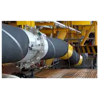 Tecalemit Flexibles stärkt ihre Präsenz im Energiesektor
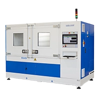 Ein Impulsbank mit außergewöhnlichen Fähigkeiten
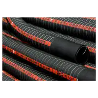 Zulassungen für flexible Schläuche für den Transport gefährlicher Güter
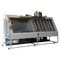 Entgiftungsanlage nach unserem Entwurf für flexible Rohrleitungen für hydraulische Flüssigkeiten
 Zertifizierung des Typs BV für feuerbeständige Schläuche für Marine und Offshore
Druckanschlüsse männliche Einbauanschlüsse
Glatte Kappe
Druckanschluss mit glatter Kappe

| Serien d (mm) | Maximaldruck | Abmessungen | Mit Kunststoffkappe | Mit Metallkappe | ||
| L (mm) | L1 (mm) | |||||
| 6 | 630 bar | 20 | 57 | 620.03.006.50 | 620.03.006.51 | |
| 8 | 630 bar | 20 | 57 | 620.03.008.50 | 620.03.008.51 | |
| 10 | 630 bar | 20 | 57 | 620.03.010.50 | 620.03.010.51 | |
| 12 | 630 bar | 26 | 60 | 620.03.012.50 | 620.03.012.51 | |
Männliche Implantation
Druckanschluss mit männlicher Implantation
Kunststoffkappe | Metallkappe | Edelstahl mit Metallkappe |
 |  |  |
| Gewinde G | Dichtungstyp | Maximaldruck | Abmessungen | Mit Kunststoffkappe | Mit Metallkappe | EDELSTAHL AISI 316 DIN 1.4436 | ||
| L(mm) | Ch.(mm) | J±0,2(mm) | ||||||
| M10 x 1 | FORM A | 400 bar | 38 | 17 | 8 | 620.01.010.50 | 620.01.010.51 | 625.01.010.50 |
| ISO228 G 1/4" | FORM A | 400 bar | 38 | 19 | 12 | 620.01.204.50 | 620.01.204.51 | 625.01.204.50 |
| M12 x 1.5 | FORM B | 400 bar | 38 | 17 | 12 | 620.01.012.10 | 620.01.012.11 | 625.01.012.10 |
| ISO228 G 1/8" | FORM B | 400 bar | 38 | 17 | 8 | 620.01.202.10 | 620.01.202.11 | 625.01.202.10 |
| ISO228 G 1/4" | FORM B | 400 bar | 38 | 19 | 12 | 620.01.204.10 | 620.01.204.11 | 625.01.204.10 |
| UNI 7707 M10x1 | FORM C | 400 bar | 38 | 17 | 8 | 620.01.010.30 | 620.01.010.31 | 625.01.010.30 |
| ISO 7/1 R 1/8" | FORM C | 400 bar | 36 | 17 | 8 | 620.01.202.30 | 620.01.202.31 | 625.01.202.30 |
| ISO 7/1 R 1/4" | FORM C | 630 bar | 36 | 17 | 12 | 620.01.204.30 | 620.01.204.31 | 625.01.204.30 |
| ISO 7/1 R 3/8" | FORM C | 630 bar | 36 | 22 | 12 | 620.01.206.30 | 620.01.206.31 | 625.01.206.30 |
| 1/8"-27 NPTF | FORM C | 400 bar | 36 | 17 | 9.5 | 620.01.302.30 | 620.01.302.31 | 625.01.302.30 |
| 1/4"-18 NPTF | FORM C | 630 bar | 36 | 17 | 14 | 620.01.304.30 | 620.01.304.31 | 625.01.304.30 |
| 3/8"-18 NPTF | FORM C | 630 bar | 36 | 22 | 14.2 | 620.01.306.30 | 620.01.306.31 | 625.01.306.30 |
| M10 x 1 | FORM E | 400 bar | 38 | 17 | 8 | 620.01.010.20 | 620.01.010.21 | 625.01.010.20 |
| M12 x 1.5 | FORM E | 630 bar | 38 | 17 | 12 | 620.01.012.20 | 620.01.012.21 | 625.01.012.20 |
| M14 x 1.5 | FORM E | 630 bar | 38 | 19 | 12 | 620.01.014.20 | 620.01.014.21 | 625.01.014.20 |
| M16 x 1.5 | FORM E | 630 bar | 38 | 22 | 12 | 620.01.016.20 | 620.01.016.21 | 625.01.016.20 |
| ISO228 G 1/8" | FORM E | 400 bar | 38 | 17 | 8 | 620.01.202.20 | 620.01.202.21 | 625.01.202.20 |
| ISO228 G 1/4" | FORM E | 630 bar | 38 | 19 | 12 | 620.01.204.20 | 620.01.204.21 | 625.01.204.20 |
| ISO228 G 3/8" | FORM E | 630 bar | 38 | 22 | 12 | 620.01.206.20 | 620.01.206.21 | 625.01.206.20 |
| M8 x 1 | FORM F | 250 bar | 38 | 17 | 8.5 | 620.01.008.00 | 620.01.008.01 | 625.01.008.00 |
| M10 x 1 | FORM F | 630 bar | 38 | 17 | 9.5 | 620.01.010.00 | 620.01.010.01 | 625.01.010.00 |
| M14 x 1.5 | FORM F | 630 bar | 38 | 19 | 12 | 620.01.014.00 | 620.01.014.01 | 625.01.014.00 |
| 7/16"-20 UNF | FORM F | 630 bar | 38 | 17 | 11 | 620.01.404.00 | 620.01.404.01 | 625.01.404.00 |
| * 1/2"-20 UNF | FORM F | 630 bar | 38 | 17 | 11 | 620.01.405.00 | 620.01.405.01 | 625.01.405.00 |
| 9/16"-18 UNF | FORM F | 630 bar | 38 | 19 | 12 | 620.01.406.00 | 620.01.406.01 | 625.01.406.00 |
| 3/4"-16 UNF | FORM F | 630 bar | 38 | 22 | 14 | 620.01.408.00 | 620.01.408.01 | 625.01.408.00 |
| JIS 2351 G 1/4" | FORM F | 630 bar | 38 | 19 | 12 | 620.01.204.00 | 620.01.204.01 | 625.01.204.00 |
| ISO228 G 1/4" | BS 5200 | 630 bar | 38 | 19 | 12 | 620.01.204.80 | 620.01.204.81 | 625.01.204.80 |
| * Auf Anfrage Für Poppet-Ventile ändern Sie die ersten drei Ziffern der Referenz: 625… zu 626… | ||||||||
S12,65X1,5
Druckanschluss mit männlicher Implantation S12,65X1,5

| Gewinde G | Dichtung | Maximaldruck | Abmessungen | Code | ||
| L(mm) | Ch.(mm) | J±0,2(mm) | ||||
| M 8 x 1 | Form F | 250 bar | 30 | 14 | 8.5 | 612.01.008.01* |
| M 10 x 1 | Form F | 630 bar | 30 | 14 | 8.5 | 612.01.010.01* |
| ISO 228 G 1/4” | Form E | 630 bar | 29 | 19 | 10 | 612.01.204.21* |
| Für einen Kunststoffstopfen ersetzen Sie die letzte Ziffer durch 0 | ||||||
M16X1,5
Druckanschluss mit männlicher Implantation M16X1,5

| Gewinde G | Dichtung | Maximaldruck | Abmessungen | Code | ||
| L(mm) | Ch.(mm) | J±0,2(mm) | ||||
| ISO 228 G 1/4” | Form E | 630 bar | 38 | 19 | 10 | 615.01.204.21 |
M16X12
Druckanschluss mit männlicher Implantation M16X12

| Gewinde G | Dichtung | Maximaldruck | Abmessungen | Code | ||
| L(mm) | Ch.(mm) | J±0,2(mm) | ||||
| ISO 228 G 1/4” | Form E | 630 bar | 49 | 19 | 10 | 621.01.204.23 |